Furniture and Appliance Drawings for House Plans
How To utilise Appliances Symbols for Building Plan
Having lots of design symbols such every bit bathroom, kitchen, appliances, cabinets, edifice cadre, electrical and telecom, garden accessories, furniture, wall, crush and structure, cubicles, function equipment, office accessories, office furniture, wall, planting, windows, doors and other for creating the floor plans for some house, buffet or office can be very helpful for making the great looking interior plan in a short period of time having our software ConceptDraw DIAGRAM as well as ConceptDraw STORE. The numerous libraries which were created in advance and which consist of so many different design elements, as well as the samples and templates for helping our new users to draw their very outset layouts, are always useful for those who are very good at making similar design plans too.
Appliances Symbols for Building Programme
You lot can create building plans using the library of Appliances Symbols of the domicile appliances manufacturers, abode appliances online, domicile appliances sale.
ConceptDraw is intuitive building program software for creating great-looking function layout and commercial floor plans includes appliances, bath kitchen, building cadre, cabinets, electrical and telecom, furniture, garden accessories, wall, shell and structure, cubicles, function accessories, office equipment, part furniture, planting, wall, door and window.

Case 1. Appliances Symbols for Edifice Plan
The kitchen layout is the view that is made by the disposition of the article of furniture, kitchen appliances, such as stove, refregerator, dishwasher, java machine, water libation etc. When designing your kitchen layout and selecting the best solution for your business firm, one of the main points is the overall layout of the kitchen and its appliances.

Case 1. Bath Appliances Symbols for Edifice Plan
Using design elements provides by the Appliances libraries, that is included into ConceptDraw Floor Plans solution you can easily develop all-time layout for your kitchen, bathroom and laundry.
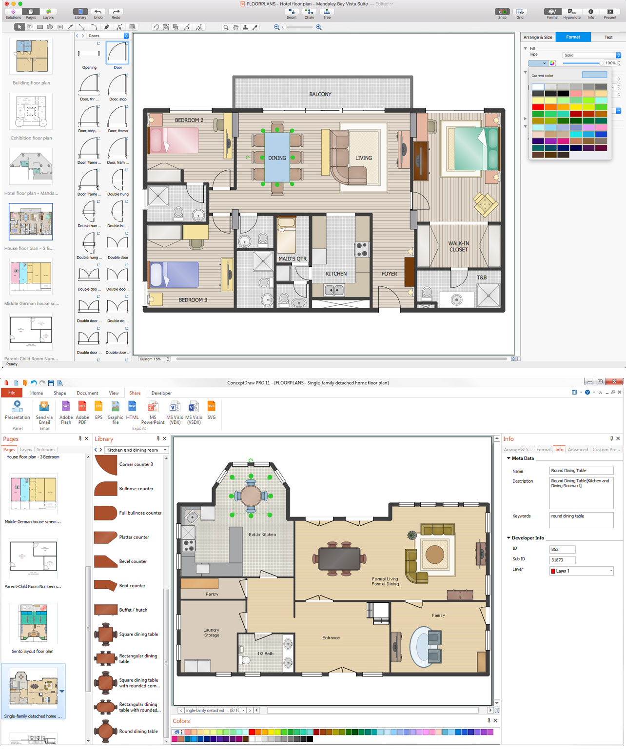
Example three. Home Appliances Layout Floor Plan
This sample is created using ConceptDraw DIAGRAM diagramming software enhanced with Edifice Plans solution from ConceptDraw Solution Park.
Ten RELATED HOW TO's:
Electrical Symbols — Rotating Equipment →
Electrical rotating machines, such as motors and generators, are vital avails for whatever ability found or large industrial visitor. An electric motor is an electrical machine that converts electric free energy into mechanical energy. The reverse of this would be the conversion of mechanical energy into electrical energy and is done past an electrical generator. In normal motoring fashion, most electric motors operate through the interaction betwixt an electric motor's magnetic field and winding currents to generate strength within the motor. In certain applications, such as in the transportation industry with traction motors, electric motors can operate in both motoring and generating or braking modes to also produce electrical energy from mechanical free energy. 26 libraries of the Electrical Engineering Solution of ConceptDraw DIAGRAM make your electrical diagramming elementary, efficient, and effective. You tin simply and rapidly driblet the ready-to-use objects from libraries into your document to create the electrical diagram. 
Movie: Electrical Symbols — Rotating Equipment
Related Solution:
Wiring Diagrams with ConceptDraw DIAGRAM →
Information technology is important to have an electrical circuits scheme, when you plan a renovation or motion to a new apartment. You accept to adapt interior co-ordinate to that plan, and it'southward trouble-free to create wiring diagrams with ConceptDraw DIAGRAM , furthermore, this software has all the features needed to create an interior program every bit well. So, get inspired by tons of examples included to ConceptDraw DIAGRAM solutions, and start your diagramming experience! A wiring diagrams, that are represented on this drawing was created to depict the components of the electric circuit schemes. These diagrams are created to depict the information about circuit arrangements and connections. Wiring diagrams, in dissimilarity to physical drawings, use standard symbol'southward notation to draw unlike circuit devices and connections. That is why, wiring diagrams are applied to discover and repair electrical and electronic circuits. The vector graphic objects provided by ConceptDraw Electrical Applied science solution can help any specialist in electric engineering science to pattern electrical schemes, circuit and wiring plans, power systems charts, and Maintenance and Repair diagrams. 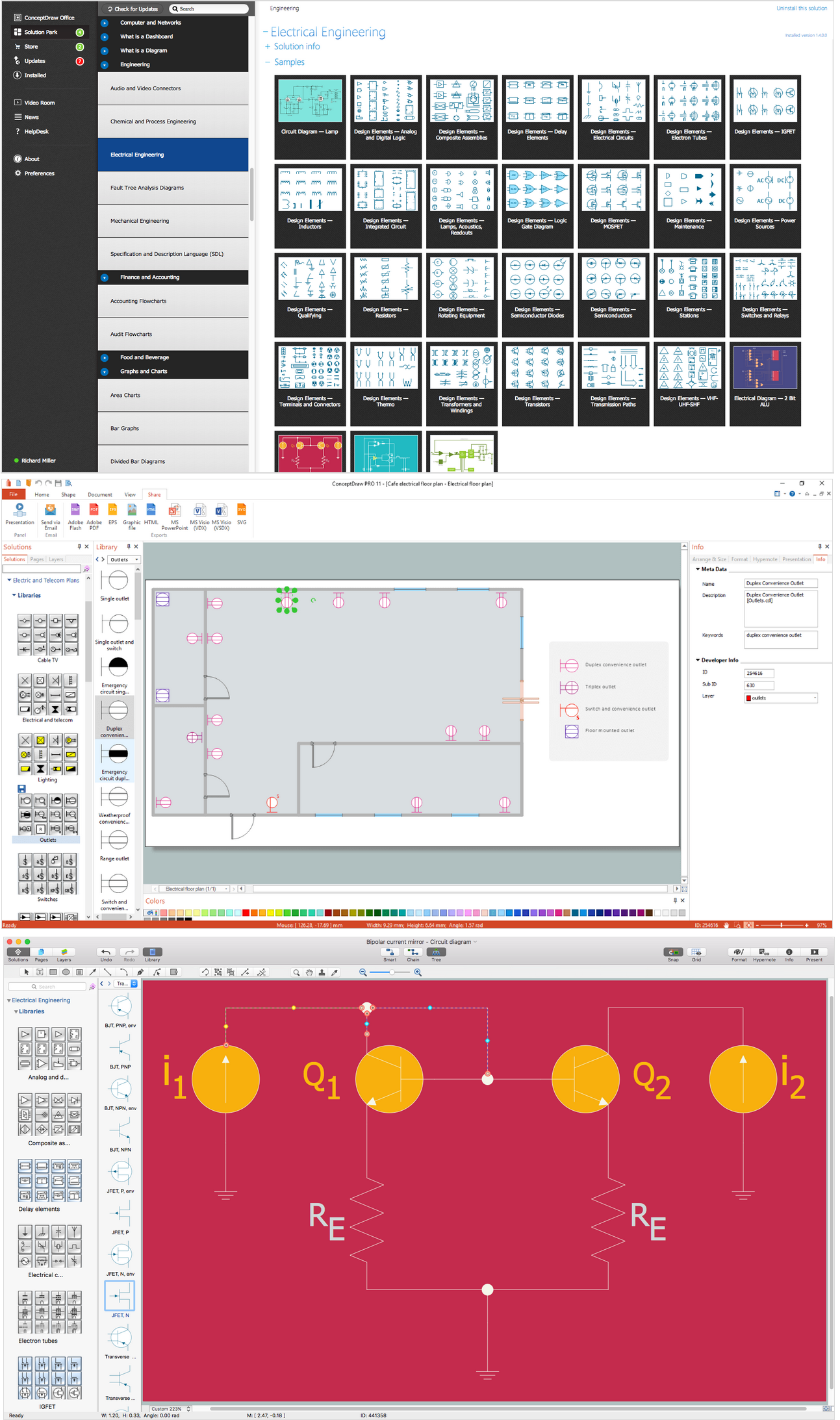
Picture: Wiring Diagrams with ConceptDraw DIAGRAM
Related Solution:
Electrical Symbols — Maintenance →
Electrical maintenance - troubleshooting electrical circuit. The diagrams are a large help when workers endeavor to observe out why a circuit does non work correctly. 26 libraries of the Electric Engineering Solution of ConceptDraw DIAGRAM make your electrical diagramming simple, efficient, and effective. Yous tin can simply and apace drop the ready-to-use objects from libraries into your document to create the electric diagram. 
Picture show: Electrical Symbols — Maintenance
Related Solution:
Fire Exit Plan. Edifice Plan Examples →
It'due south very important for whatsoever establishment to have a fire exit programme and to train it several times a year. The plan must be put on each floor of the building in a way that information technology could exist easily seen. To make the plan articulate and descriptive, y'all should await through examples and so create 1 for you your building. Find out the fire go out plan instance created with ConceptDraw DIAGRAM and its Fire and Emergency Plans solution. This plan is a floor plan that shows the ways in which people inside the edifice can be evacuated in the event of a fire. The location of telephones, fire extinguishers and first aid kits are indicated on the fire exit plan. The Legend in the lower right corner of the plan makes it clear and easy-to-read. Such plan should exist placed on the wall on each flooring of the building. 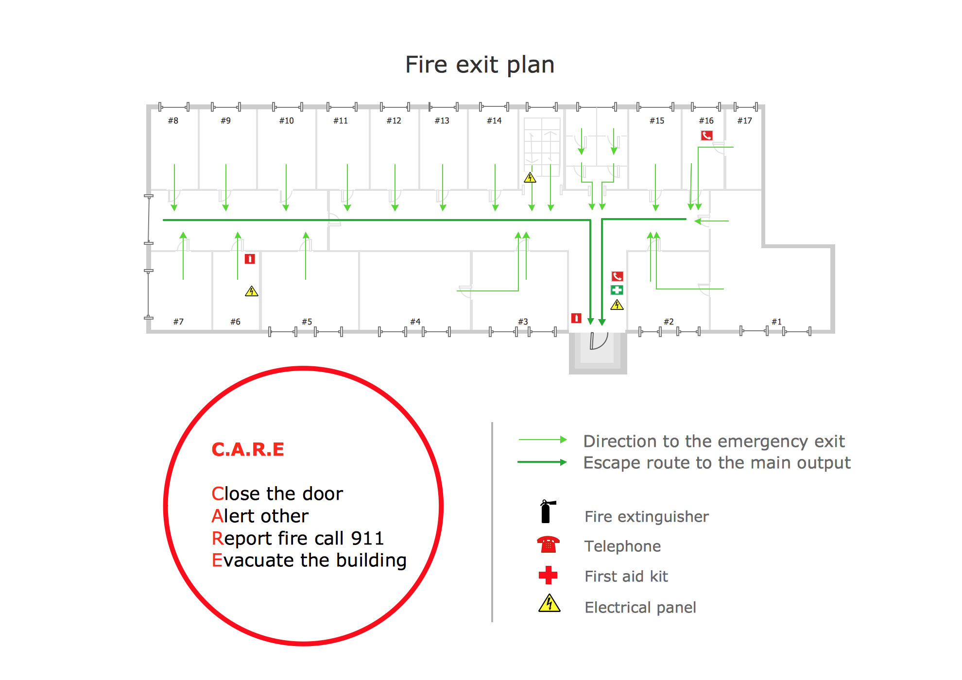
Picture: Fire Exit Plan. Building Plan Examples
Related Solution:
Comparison ConceptDraw DIAGRAM to Omnigraffle →
Comparing ConceptDraw DIAGRAM to Omnigraffle - Cantankerous-platform product. While about cartoon tools are designed for use on one operating system, ConceptDraw DIAGRAM is available equally two independent and concurrent versions on both Macintosh (macOS) and PC (Windows). License is per named user. That means you can apply a single license for Macintosh and PC. Users can install at work and at dwelling house with a single license. 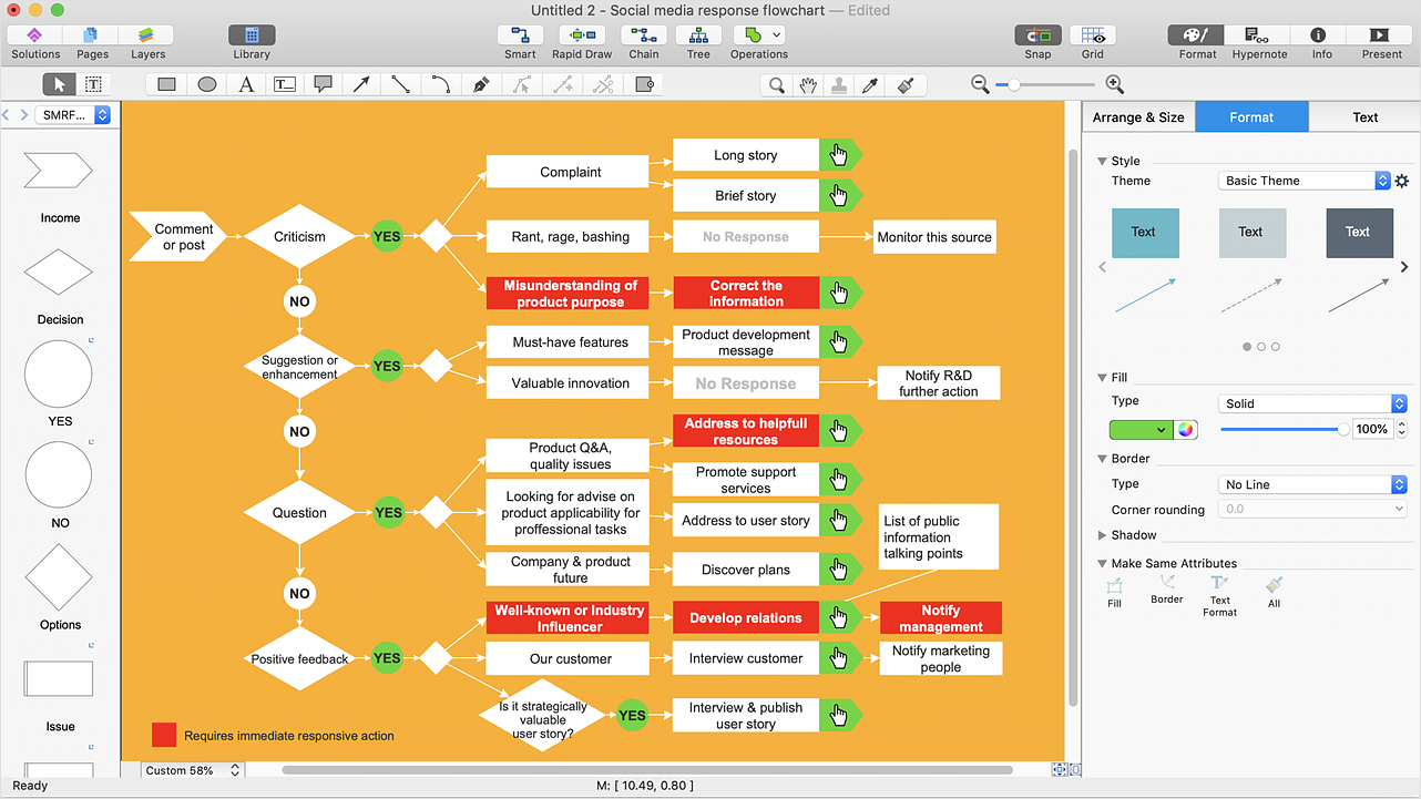
Pic: Comparing ConceptDraw DIAGRAM to Omnigraffle
Related Solution:
Electrical Symbols — Switches and Relays →
In electrical engineering, a switch is an electrical component that can break an electrical circuit, interrupting the current or diverting it from one conductor to another. The mechanism of a switch may be operated directly by a human operator to control a circuit (for example, a lite switch or a keyboard button), may exist operated by a moving object such as a door-operated switch, or may exist operated past some sensing element for pressure, temperature or menses. A relay is a switch that is operated by electricity. Switches are made to handle a wide range of voltages and currents; very large switches may be used to isolate high-voltage circuits in electrical substations. 26 libraries of the Electrical Engineering Solution of ConceptDraw DIAGRAM brand your electrical diagramming uncomplicated, efficient, and effective. Y'all tin can simply and speedily drop the ready-to-use objects from libraries into your document to create the electrical diagram. 
Picture: Electric Symbols — Switches and Relays
Related Solution:
Swim Lane Flowchart Symbols →
Utilise the set of special professionally developed swim lane flowchart symbols - single, multiple, vertical and horizontal lanes from the Swimlanes and Swimlanes BPMN 1.2 libraries from the Business organisation Process Diagram solution, the Swim Lanes library from the Business Process Mapping solution as the perfect basis for your Swim Lane Flowcharts of processes, algorithms and procedures. 
Picture: Swim Lane Flowchart Symbols
Related Solution:
Audio and Video Connections Explained →
The Audio and Video Connectors solution contains a set of video connectors, audio connectors and south video connectedness; you will as well find pre-designed objects, libraries, templates, and samples, allowing quick and piece of cake diagramming of diverse configurations of sound and video devices. 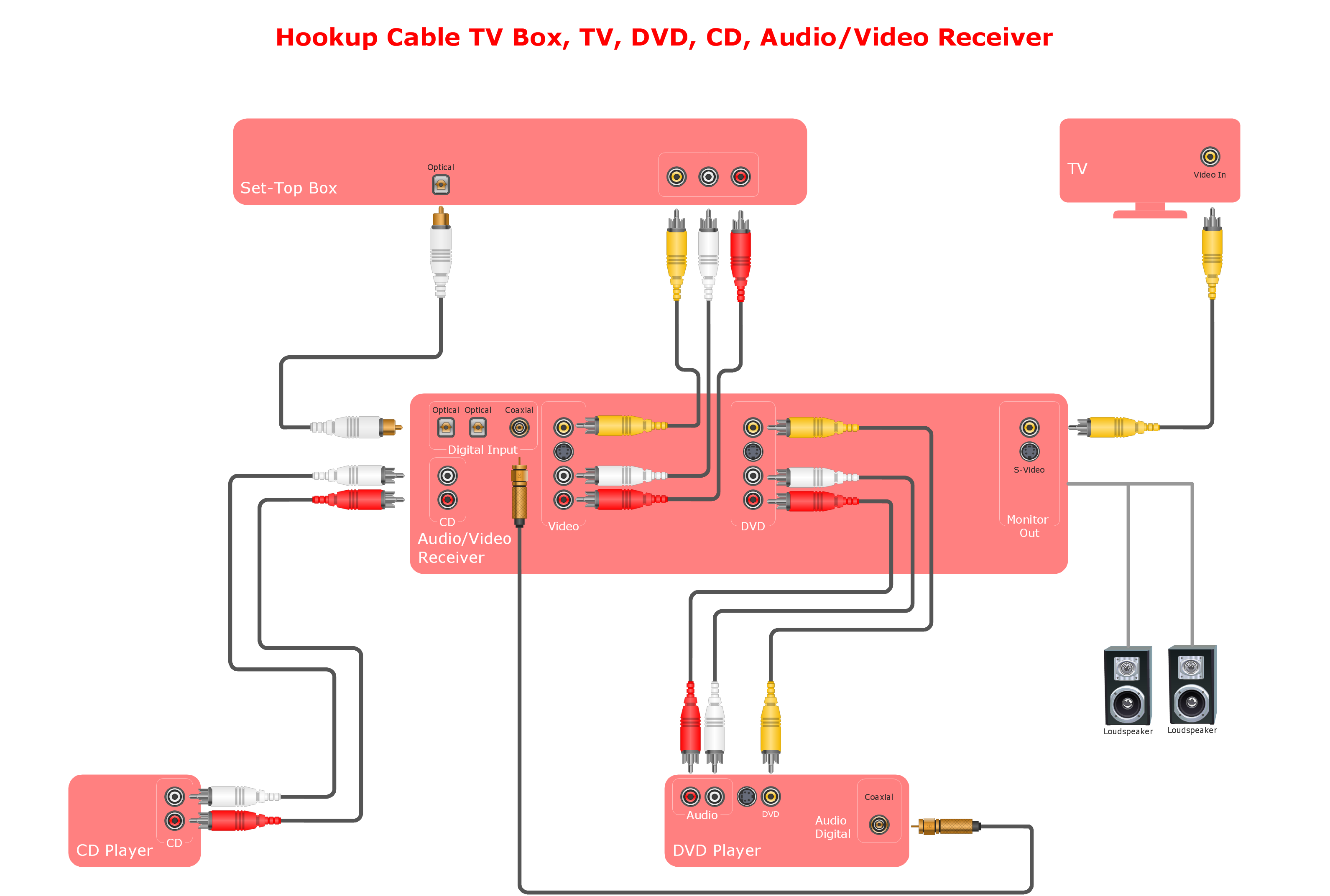
Flick: Audio and Video Connections Explained
Related Solution:
Procedure Flowchart →
When trying to effigy out the nature of the problems occurring within a project, there are many ways to develop such understanding. Ane of the well-nigh mutual means to certificate processes for further improvement is to draw a process flowchart, which depicts the activities of the process arranged in sequential social club — this is business procedure management. ConceptDraw DIAGRAM is business concern process mapping software with impressive range of productivity features for business procedure direction and classic project management. This business organisation process management software is helpful for many purposes from unlike payment processes, or manufacturing processes to chemical processes. Business organization procedure mapping flowcharts helps clarify the actual workflow of dissimilar people engaged in the aforementioned process. This samples were made with ConceptDraw DIAGRAM — business concern process mapping software for flowcharting and used as classic visio alternative because its briefly named "visio for mac" and for windows, this sort of software named the business process management tools. This flowchart diagram shows a procedure menstruum of project management. The diagram that is presented hither depicts the project life cycle that is basic for the most of project direction methods. Breaking a project into phases allows to track it in the proper manner. Through separation on phases, the total workflow of a project is divided into some foreseeable components, thus making information technology easier to follow the project status. A project life cycle unremarkably includes: initiation, definition, design, development and implementation phases. Distinguished method to prove parallel and interdependent processes, also as project life bike relationships. A flowchart diagram is oft used as visual guide to project. For instance, it used by marketing project management software for visualizing stages of marketing activities or as project management workflow tools. Created with ConceptDraw DIAGRAM — business organization process mapping software which is flowcharting visio culling or shortly its visio for mac, this sort of software platform frequently named the concern process management tools. 
Picture: Procedure Flowchart
Related Solution:
How To Create Home Programme with Examples →
Designing a floor plan or a home plan using special software may audio quite complicated. There are many tools to create such plan, simply it would be useful for a beginner to watch some tips on how to create dwelling plan with examples or even templates. ConceptDraw Solution Park provides dozens of floor plans examples, templates and libraries with vector stencils. This small private apartment flooring plan is created using ConceptDraw Building Plans solution. It provides the 15 object libraries that include more 600 vector objects along with the set of templates for drawing different floor plans. The given sample represents the individual apartment'south plan in details. It shows the layout of rooms, the furniture and sanitary engineering location and even possible location of houseplants. The legend on the correct side of the drawing will guide people through the location of the flat. 
Picture: How To Create Home Plan with Examples
Related Solution:
Source: https://www.conceptdraw.com/How-To-Guide/appliance
0 Response to "Furniture and Appliance Drawings for House Plans"
Postar um comentário